| www.elfly.pl | ||
Ostatnio dodane / Last added |
||
 |
 |
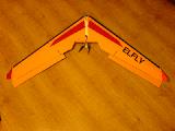 |
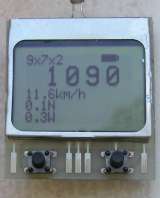
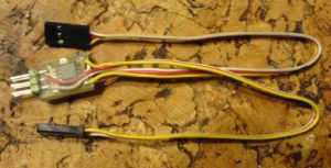
| Tachometr / Tachometer | ELEVON Mixer | TZagi by Zbig |
>>wersja polska<<
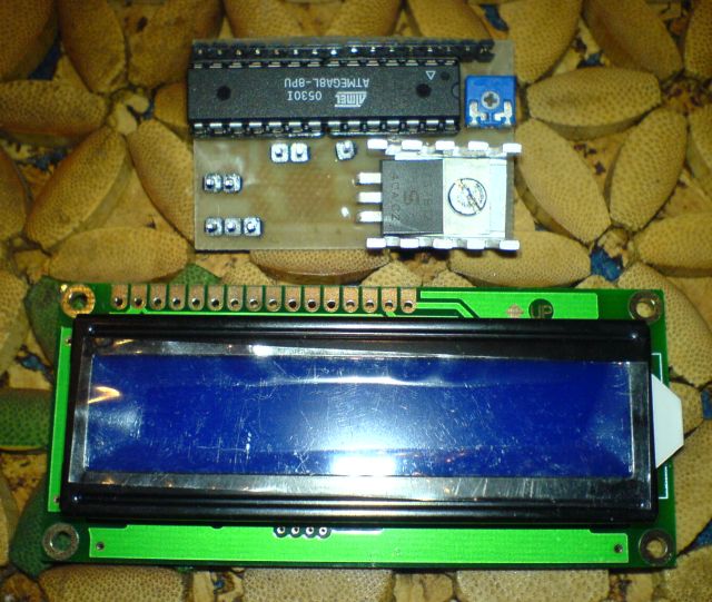
MULTIMETER (PDIP ATMega8 version)
There are information on this page necessary to build multimeter using PDIP package ATMega8 chip. Description of the base multimeter version you can find HERE. You should familiarize with base multimeter version, if you intend to build the PDIP one.
 |
 |
 |
 |
 |
 |
click on picture to englare
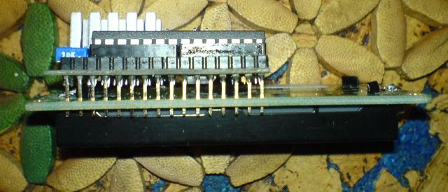
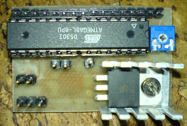
Construction
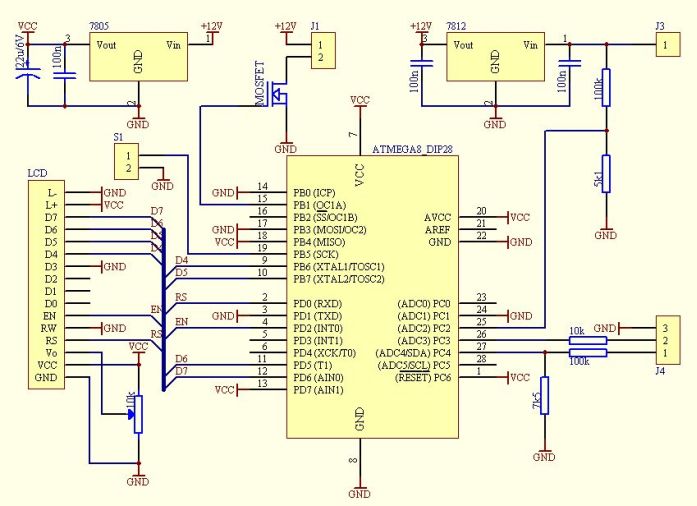
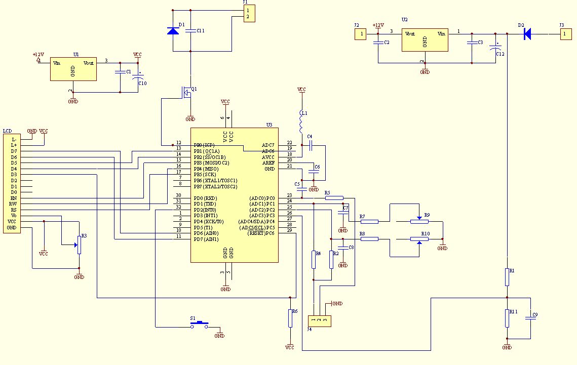
Schematic
Part List
| Element | Value/Type | Case | Remars |
| Resistor | 100k | 1206 | x2 |
| Resistor | 7k5 | 1206 | |
| Resistor | 5k1 | 1206 | |
| Resistor | 10k | 1206 | |
| Potentiometer | 10k | LCD contrast adjustment | |
| Capacitor | 100n | 1206 | x3 |
| Capacitor | 22u/6V | SMD A | |
| Voltage regulator +5V |
7805 | TO-252 | e.g. LM7805 |
| Voltage regulator +12V | 7812 | TO220 | e.g. LM7812 |
| µC | ATMEGA8 | PDIP | |
| Connectors | LCD J1, J3, J4 |
|
GOLDPIN >= 24 pins |
| Switch | S1 |
Optional element. Any kind of switch. There are only places on PCB to solder switch connector.
|
|
| Transistor | MOSFET | SOT-23 | e.g. BSS-138 (Fan current consumption <200mA) |
| Heatsink | See pictures |
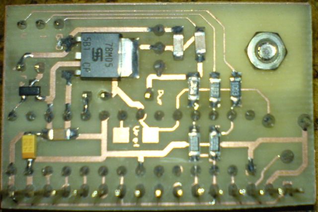
Layout - solder side

click on picture to englare
Layout - bottom side
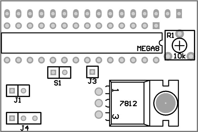
click on picture to englare
Picture of PCB is here. There are two version of PCB - normal and mirrored. I think, that anyone who makes PCBs will know, which one schould be used to produce right PCB.
Programing
PDIP ATMega8 chip programming is a standard routine. More information you can find for example here.
I prepared some multimeter code versions:
| LCD 1x16 | HEX | |
 |
LCD 2x16 | HEX |
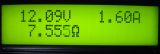 |
LCD 2x16 Load resistance displaying |
HEX |
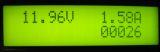 |
LCD 2x16 Capacity in mAh passed to load displaying |
HEX |
 |
LCD 2x16 Load resistance and capacity in mAh passed to load displaying |
HEX |
Caution! Wrong code (e.g. TQFP mutlimeter version) can damage µC chip
Instalation in PSU and
Regulation
Connect PDIP multimeter to PSU the same way like TQFP one.
Złącza i elementy regulacyjne:
| ELEMENT | ACTION |
| S1 | reset/setup connector During normal work short S1 circuit cancel amount of displayed charge. In versions without charge displaying, short S1 circuit doesn't make any reaction. To enter setup push and hold S1 switch (short S1 circuit), then power on multimeter. When "www.elfly.pl" appear on LCD, you are in setup mode. First parameter to adjust is ATMega8 voltage reference. Reference voltage inaccurracy is the main measurement error factor in previous multimeter code versions, because Vref vary from chip to chip in quite wide range . You can measure reference voltage between multimeter ground and µC pin no. 21. There are special pads on PCB marked "Vref" to make it easily. Measured value you should write down in setup. If you don't write anything, it will be assumed, that Vref=2.56V (due to datasheet). After Vref setup, button must not be pressed for about 5 seconds. The next parameter to set up is shunt resistor value. If the resistor value is known, repeat button pushing until correct value reached. If resistor value is unknown (e.g. self made resistor), short PSU output by ammeter, set some current by PSU current limit regulator and then, push button, lead to equal current indication on ammeter and multimeter. After shunt resistor value setup, button must not be pressed for about 5 seconds. The next parameter to set up is voltage. Because PDIP version doesn't have potentiometer to adjust input voltage divider, you have to do it in soft manner. Simply connect voltmeter to PSU output and pushing S1 lead to equal voltage indication on ammeter and multimeter. After voltage setup, button must not be pressed for about 5 seconds. The next parameter to set up is fan switch-on power threshold. It is the real power loosed on output transistor (transistors), because multimeter has information on voltage drop on transistor and driving current. To avoid instability switch-off threshold is automatically set to 20% less than switch-on one. |
| R1 | LCD contrast potentiometer. Turn that potentiometer first, if nothing is visible on LCD. |
| J1 | Fan
connector. Pin no. 1: Fan "+" Pin no. 2: Fan "-" |
| J3 | +35V Rectifier bridge voltage. See U2 element you used data sheet to know about maximum voltage it can work properly. On the other hand the minimum voltage on that pin mustn't drop bellow c.a. 9V, or 6.5V if low drop type U2 and U3 voltage regulators were used. That pin should be connected even if +12V DC is connected to J2 pin. Voltage from that pin deliver information for fan switching. |
| J4 | Measuring signal connector. Multimeter is suitable for voltage and current measurement in PSU, where current sense shunt resistor is connected in series with load and is in negative rail. Pin no.1: voltage measurement U - connect to "+" PSU output, best directly to output terminal; Pin no.2: current measurement I - connect to "-" PSU output, best directly to output terminal; Pin no.3: ground - connect to shunt resistor terminal opposite to that connected to "-" PSU output. |
| LCD | LCD connector. Multimeter works properly with LCD's 1x16 logical controlled as 2x8 (most of LCD's available on the market). Because of linear voltage regulators used in multimeter, sourcing current is limited. Main current consumption elements are fan and LCD backlight, so: - use LCD with LED backlight (typically current consumption is less than 15mA); - use low speed, low current fan. Additional advantage of that solution will be silence. |